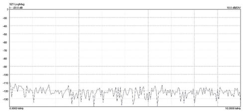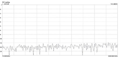
6 GHz Vector Network Analyser
- 300 kHz to 6 GHz operation
- High speed of > 5000 dual port S-parameters per second
- Quad RX four-receiver architecture for best accuracy
- 118 dB dynamic range at 10 Hz bandwidth
- 0.005 dB RMS trace noise at maximum bandwidth of 140 kHz
- Half-rack, small-footprint, lightweight package
- PC-controlled over USB from a Microsoft Windows interface
- Reference plane offsetting and de-embedding
- Time domain and port impedance transformations
- Tabular and graphic print and save formats, including Touchstone
- P1dB, AM to PM, and stand-alone signal generator utilities
- Fully accessible, guided 8 and 12-term calibration processes
- 6 calibration modes, including unknown through and connected DUT isolation
- Vector Network Analysis For The Many
- Vector Network Analysis Everywhere
- Quad RX Four-receiver Architecture
- Support for 8 and 12-term Calibration and The Unknown through
- Bias-Ts
- Other I/O
- Test Cables and Calibration Standards
- Phase and Amplitude-stable Test Leads
- Test Port Adaptors
- Calibration and Measurement Reference Standards
- Test Leads and Calibration Standards Selection Guide
- PicoVNA 2 Software
- Supported Calibrations
- Reference Plane Extension
- De-embedding Embedded Port Interfaces
- Z0 Impedance Reference
- Time Domain Transmission and Reflectometry Measurements
- P1dB Utility
- AM to PM Conversion Utility
- Limit Lines Testing
- Pricing
Vector Network Analysis For The Many
Once the domain of an elite few, microwave measurement has encroached into the lives of scientists, educators, surveyors, inspectors, engineers and technicians alike. Today's microwave measurements need to be straightforward, portable, accurate, cost-effective and easy to learn.
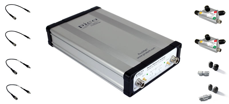
The PicoVNA 106 is an all new, UK-designed, professional USB-controlled, laboratory grade vector network instrument of unprecedented performance, portability and value for money. Despite its simple outline, small footprint and low cost, the instrument boasts a four-receiver architecture to minimize the uncorrectable errors, delays and unreliability of internal transfer switches.
Despite its small size, the PicoVNA 106 delivers an exceptional dynamic range of 118 dB at 10 Hz and only 0.005 dB RMS trace noise at its maximum operating bandwidth of 140 kHz. It can also gather all four S-parameters at every frequency point in just 190 µ in other words, a 500 point 2-port .s2p Touchstone file in less than a tenth of a second. Its low price means that the PicoVNA 106 would be cost-effective as a deep dynamic range scalar network Analyser or a single-port vector reflectometer. However, despite its size and price, the PicoVNA 106 really is a full-function dual-port, dual-path vector network Analyser. It's affordable in the classroom, in small businesses and even in amateur workshops, yet capable of meeting the needs of all users up to the microwave laboratory technician and expert.
Vector Network Analysis Everywhere
The PicoVNA's small size, weight and cost, and high performance suit it to field service, installation test, embedded and classroom applications. With its remote automation capability, it's also attractive in applications such as:
- Test automation
- Manufacturers needing to integrate a reflectometry or transmission measurement core
- Inspection, test, characterization and calibration in the manufacture, distribution and service center industries
- Electronics component, assembly and system, and interface/interconnect ATE (cable, PCB and wireless)
- Material, geological, life science and food sciences; tissue imaging; penetrating scan and radar
- Broadband cable and harness test at manufacture, installation and fault-over-life monitoring
- Antenna matching and tuning
Quad RX Four-receiver Architecture
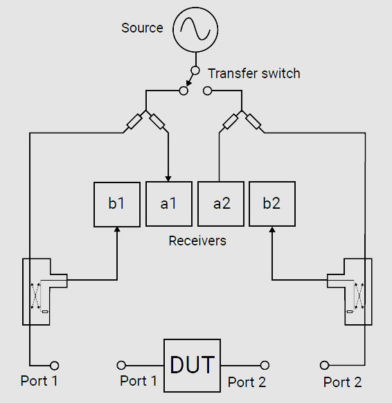
In a VNA a swept sine-wave signal source is used to sequentially stimulate the ports of the interconnect or device under test. The amplitude and phase of the resultant transmitted and reflected signals appearing at both VNA ports are then received and measured. To wholly characterize a 2-port device under test (DUT), six pairs of measurements need to be made: the amplitude and phase of the signal that was emitted from both ports, and the amplitude and phase of the signal that was received at both ports for each source. In practice this can be achieved with a reasonable degree of accuracy with a single source, a transfer switch and two receivers; the latter inputs being switched through a further pair of transfer switches. Alternatively three receivers can be used with an additional input transfer switch or, as in the PicoVNA, four receivers can be used. Using four receivers eliminates the receiver input transfer switch errors (chiefly leakage and crosstalk) that cannot be corrected. These residual errors are always present in two- and three-receiver architectures and lead to lower accuracy than that of the Quad RX design.
Support for 8 and 12-term Calibration and The Unknown through
Almost all vector network Analysers are calibrated for twelve error sources (six for each signal direction). This is the so-called 12-term calibration, which experienced VNA users are used to performing fairly regularly. In a four-receiver design some error sources are so reduced that 8-term calibration becomes possible, along with an important and efficient calibration technique known as the unknown through. This gives the ability to use any through interconnect (including the DUT) during the calibration process, vastly simplifying the procedure and reducing the number of costly calibration standards that need to be maintained.
Bias-Ts
Bias-Ts are often not provided, or available as costly extras, on other VNAs. Use the PicoVNA 106's built-in bias-Ts to provide a DC bias or test stimulus to active devices without the complexity and cost of external DC-blocks. The bias is supplied from external power supplies or test sources routed to the SMB connectors adjacent to each VNA port.
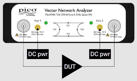
Use to power an active DUT
Other I/O
Power (12 to 15 V DC @ 22 W) and USB 2.0 control are located on the rear panel. Trigger I/O for sweep synchronization and 10 MHz I/O for reference clock synchronization are available on four BNC sockets.
Test Cables and Calibration Standards
A range of RF and Microwave accessories are available from Pico Technology. Test cables and calibration standards have particular significance to the overall performance of a VNA, so we recommend that you select your accessories carefully.
Cables and standards are often the weakest links in a VNA measurement, generally contributing significantly to measurement uncertainty despite their high cost. At the lowest levels of uncertainty, costs can be significant and measurements can be compromised by seemingly quite minor damage or wear. For these reasons, many customers hold both premium-grade items for calibration, reference or measurement standards, and standard-grade items as working or transfer standards and cables. Pico Technology can now offer cost-effective solutions in both grades.
Phase- and Amplitude-stable Test Leads
Two test cable types and grades are recommended and provided by Pico Technology. Both of high quality, with robust construction and stainless steel connectors, the main difference between them is the stability of their propagation velocity and loss characteristic when flexed; that is, the degree to which a measurement could change when the cables are moved or formed to a new position. Cables are specified in terms of flatness and phase variation at up to 6 GHz when a straight cable is formed as one 360° turn around a 10 cm mandrel. Standard test cables are highly flexible. The premium flex-form cables are also flexible but tend to hold their form until intentionally moved to a new position. This further enhances repeatability for bench measurements at fixed port locations or for test installations.
| Order code | Performance | Connectors | Construction | Dielectric | Ø over jacket |
Impedance (Ω) |
Loss(dB) @ 6 GHz> |
Phase stability @ 6 GHz |
Amplitude stability (dB) @ 6 GHz |
Length (mm) |
TA336 |
Standard | N(m) - SMA(m) | Flexible | Low-density PTFE | 7.1 mm(0.28”) | 50 | 0.7 | 2° | 0.1 | 600 |
TA337 |
N(m) - SMA(f) | |||||||||
TA338 |
Premium | N(m) - PC3.5(m) | Flex-form | 7.5 mm(0.30”) | 0.6 | 0.08° | 0.05 | |||
TA339 |
N(m) - PC3.5(f) |
Test Port Adaptors
| Order code | Name | Grade | Impedance(Ω) | Bandwidth (GHz) | Connectors |
TA342 |
ADA-STD-MM | Standard | 50 | 18 | SMA(m-m) |
TA343 |
ADA-STD-FF | SMA(f-f) | |||
TA340 |
ADA-PREM-MM | Premium | 27 | PC3.5(m-m) | |
TA341 |
ADA-PREM-FF | PC3.5(f-f) |
Calibration and Measurement Reference Standards
Pico Technology also offers two short, open, load and through (SOLT), 4-piece, 5-port calibration kits in both male and female genders. All kits have high-performance tight-tolerance stainless steel interface connectors. Kits are supplied as an assembled five-port “Y” SOLT, either male or female. They can be disassembled for individual usage, or for economical refurbishment should a calibration standard be damaged. Each SOLT is supplied with traceable calibration data linked to the kit serial number, and is supplied in a protective carry case.
| Order code | Name | Grade | Ports | Impedance(Ω) | Bandwidth (GHz) | Connector type |
TA344 |
SOLT-STD-M | Standard | 5 short, open, load, through | 50 | 6 | SMA(m) |
TA345 |
SOLT-STD-F | SMA(f) | ||||
TA346 |
SOLT-PREM-M | Premium | PC3.5(m) | |||
TA347 |
SOLT-PREM-F | PC3.5(f) |
Test Leads and Calibration Standards Selection Guide
Test cables are typically purchased as a pair, but single replacement leads are also available. Calibration kits can be purchased as a pair or as a single kit depending on the primary (best uncertainty) measurement application and its DUT interface, and sometimes to meet a secondary purpose with other DUT interfaces. Budget may also be a consideration. Pico Technology provides for all purchase options. You can order any combination of accessories, but to get you started we recommend that you choose one of the following standard configurations.
Configuration 1: universal
For best overall test efficiency and uncertainty in a mix of single- or dual-port test application of both genders, we recommend this dual-port, insertable test lead and calibration standards configuration and the use of additional test port adaptors as necessary. All calibration modes are then available using the test lead ports or adapted test ports.
| Primary DUT interface |
Test leads required | Cal. kits required | Supported calibration modes | Example DUT | |
| Single cal. kit | Dual cal. kit | ||||
| 1. Dual-port female-male or male-female |
Male + female: TA336 + TA337 or TA338 + TA339 |
Male + female: TA344 + TA345 or TA346 + TA347 |
N/A |
All S-parameters, insertable DUT (zero length through calibration). Non-insertable via port adaptors. |
Insertable dual port component or device with male and female ports. Use port adaptors for dual-port single-gender DUT. |
Configurations 2 to 5: gender-specific and port-number-specific
The following configurations are recommended where there is a focus upon a particular DUT port or measurement arrangement.
| Primary DUT interface |
Test leads required | Cal. kits required | Supported calibration modes | Example DUT | |
| Single cal. kit | Dual cal. kit | ||||
| 2. Single-port female | Male: 1x TA336 or 1x TA338 |
Female: 1x TA345 or 1x TA347 |
Single-port reflectometry: S11 or S22 |
N/A | Component port or a device/fascia-mounted input or output port |
| 3. Single-port male | Female: 1x TA337 or 1x TA339 |
Male: 1x TA344 or 1x TA346 |
Single-port reflectometry: S11 or S22 |
N/A | Component or cable port |
| 4. Dual-port female | 2 x male: 2x TA336 or 2x TA338 |
1 or 2 female: 1x / 2x TA345 or 1x / 2x TA347 |
S21 transmission, S11 + S21 All S-parameters, non-insertable DUT. |
All S-parameters, non-insertable DUT (faster and unknown through calibration process) | Device/fascia-mounted input and output port or other dual-port measurement |
| 5. Dual-port male | 2 female: 2x TA337 or TA339 |
1 or 2 male: 1x / 2x TA344 or 1x / 2x TA346 |
S21' S1111 or S21 All S-parameters, non-insertable DUT |
All S-parameters, non-insertable DUT (faster and unknown through calibration process) | Cable |
PicoVNA 2 Software
PicoVNA 2 presents standard VNA measurement and calibration simply, intuitively and with efficient usage at its heart. The software offers a comprehensive range of measurements and plot formats in its one, two or four user-configurable measurement channels. All the standard vector network Analyser functions can be seen at a glance.
Save, recall, print, labels, calibration tools
Signal generator, P1dB and AM to PM utilities
One, two or four channels
Click or touch and drag values,
scales and markers
Table of up to
eight markers for
the selected channel
Log magnitude, Phase, Smith chart, SWR,
Group delay, Linear magnitude, Real
Imaginary, Time domain, Polar linear.
Controls, information and vector
trace math functions.
Supported Calibrations
The PicoVNA 2 software supports a comprehensive range of calibration modes to address single or dual-port workload with male, female or mixed gender interfaces, all with best achievable accuracy (least uncertainty). In some instances only a single calibration kit may be required, as outlined in the tables above.
As you would expect, the Pico calibration kits are individually serial-numbered and supplied with S-parameter data. This standard-form data is a traceable and accurate record of measured errors for the calibration kit. It can be loaded into the software, which will correct for these errors and those of the instrument during a calibration.
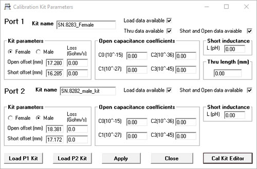
Alternatively, you can use a third-party calibration kit and its data, or you can enter its electrical length, parasitic values and polynomial coefficients into the software if these are supplied rather than a profile data set.
As for any vector network Analyser, for best accuracy a calibration is performed before a measurement with the same sweep span and frequency steps as the measurement. If, however, a change of sweep settings is necessary for a measurement, the PicoVNA 2 software will, for convenience, interpolate its corrections to the new sweep settings.
An enhanced isolation calibration setting is available for optimum dynamic range when using resolution bandwidths below around 1 kHz.
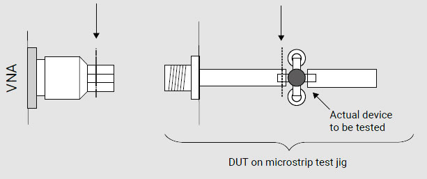
ref plane is here
the ref plane to be here
Reference Plane Extension
Reference plane extension (offset) allows you to shift the measurement reference plane away from the point established during calibration. This is useful in removing the path length of assumed ideal interconnecting , connectors cables or microstrip lines from measurements. PicoVNA 1 software allows independent reference plane extensions on each of the measurement parameters (S11, S22, S12 or S21), either as an automatic re-reference or by manual entry. Independent extensions allow, for example, different extensions on the two ports for S11 and S22 and then through-line normalization for S21 and S12 transmission comparison with equivalent length through-line.
De-embedding Embedded Port Interfaces
When it is unsafe to assume the above ideal interconnecting connectors cables or microstrip lines; for example to achieve greater accuracy or to remove known imperfections in a test setup, we can choose instead to de-embed the interface networks on each measurement port. The PicoVNA 2 software simply requires a full Touchstone .s2p file for the embedded interfacing network on each port. Likewise, defined networks can be embedded into the measurement to achieve a desired simulated measurement. As for a calibration, best accuracy will be achieved when the embedding network is defined at the same frequency points as the intended measurement. Unusually for a vector network Analyser, the PicoVNA 2 software will interpolate where necessary and possible.
Z0 Impedance Reference
System measurement impedance (default 50 Ω) can be mathematically converted to any value between 10 Ω and 200 Ω. The PicoVNA 2 software also supports the use of external matching pads and calibration in the new impedance using a calibration kit of that impedance.
Time Domain Transmission and Reflectometry Measurements
Time domain reflectometry is useful in the measurement of a transmission line; in particular the distance-to-fault location of any discontinuity due to connectors, damage or design error. To achieve this, the PicoVNA 2 software determines from its frequency domain measurements the time domain response to a step input. Using a sweep of harmonically related frequencies, an inverse fast Fourier transform of reflected frequency data (S11) gives the impulse response in the time domain. The impulse response is then integrated to give the step response. Reflected components of the step, occurring at measurable delays after excitation, indicate the type of discontinuity and (assuming a known velocity of propagation) the distance from the calibration plane.
the transmitted signal data (S21). This can be used to measure the pulse response or transition time of amplifiers, filters and other networks.
The PicoVNA 2 software supports Hanning and Kaiser-Bessel lowpass filtering on its time-domain IFFT conversions, preserving magnitude and phase, and achieving best resolution. A DC-coupled DUT is essential to the method.
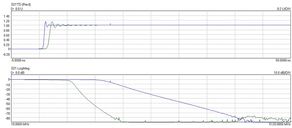
Time domain transmission step responses (top) and frequency responses (bottom) of two lowpass filters
P1dB Utility
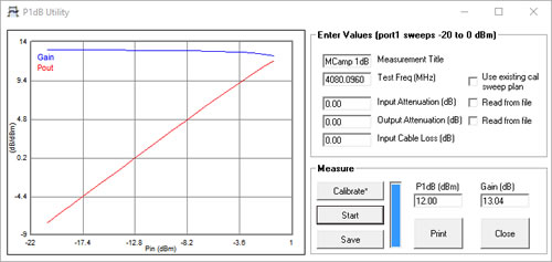
The 1 dB gain compression point of amplifiers and other active devices can be measured using a power sweep, either at a test frequency or over a sweep of test frequencies. The VNA determines the small-signal gain of the amplifier at low input power, and then increases the power and notes the point at which the gain has fallen by 1 dB. This utility uses a second-order curve fit to determine interpolated 1 dB compression points.
AM to PM Conversion Utility
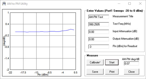
AM to PM conversion is a form of signal distortion where changes in the amplitude of a signal produce corresponding changes in the phase of the signal. This type of distortion can have serious impact in digital modulation schemes for which amplitude varies and phase accuracy is important.
Limit Lines Testing
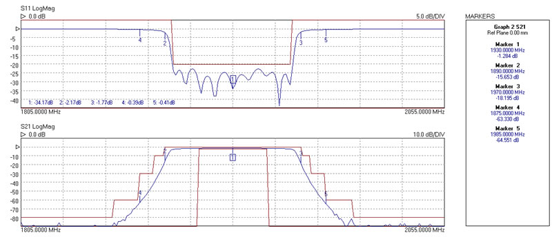
The limit lines facility allows six segments to be defined for each displayed plot. These can be extended to 11 segments using an overlapping technique. Visual and audible alarms can be given when a limit line is crossed. All plot formats except Smith chart and Polar support limit testing. Peak hold functions are also available.
Specifications
Standard conditions: 10 Hz resolution bandwidth, at -3 dBm test power, at an ambient temperature of between 20°C and 30°C but within 1°C of the calibration temperature and 60 minutes after power-up.
| Test Port Characteristics | ||
|---|---|---|
| Load match |
|
|
| Source match |
|
|
| Directivity |
|
|
| Crosstalk |
|
Corrected. Both calibrated ports terminated in short circuits. After isolation calibration. |
| Maximum input level | +10 dBm, typ | 1 dB compression |
| Maximum input level | 23 dBm | No damage |
| Impedance | 50 Ω | |
| Connectors | Type N, female | |
| Bias-T Input Characteristics | ||
|---|---|---|
| Maximum current | 250 mA | |
| Maximum DC voltage | ±15 V | |
| Current protection | Built-in resettable fuse | |
| DC port connectors | SMB(m) | |
| Sweep I/O Characteristics | ||
|---|---|---|
| Sweep trigger output voltage | Low: 0 V to 0.8 V High: 2.2 V to 3.6 V |
|
| Sweep trigger input voltage | Low: -0.1 V to 1 V High: 2.0 V to 4 V |
|
| Sweep trigger input voltage | ±6 V | No damage |
| Sweep trigger in/out connectors | BNC female on back panel | |
| Measuring Functions | ||
|---|---|---|
| Measuring parameters |
S11, S21, S22, S12 P1dB, 1 dB gain compression AM-PM conversion factor |
|
| Error correction |
12 error term full S-parameter correction (insertable DUT) 12 error term full S-parameter correction (non-insertable DUT) 8 error term full S-parameter unknown through correction (non-insertable DUT) S11 (1-port correction) De-embed (2 embedding networks may be specified), impedance conversion S21 (normalize, normalize + isolation) S21 (source match correction + normalize + isolation) Averaging, smoothing Hanning and Kaiser-Bessel filtering on time-domain measurements Electrical length compensation (manual) Electrical length compensation (auto) Effective dielectric constant correction |
|
| Display channels | 4 channels | |
| Traces | 2 traces per display channel | |
| Display formats | Amplitude (logarithmic and linear), Phase, Group Delay, VSWR, Real, Imaginary, Smith Chart, Polar, Time Domain | |
| Memory trace | One per display channel | |
| Limit lines | 6 segments per channel (overlap allowed) | |
| Markers | 8 markers | |
| Marker functions | Normal, Δ marker, fixed marker, peak / min. hold, 3 dB and 6 dB bandwidth | |
| Sweep Functions | ||
|---|---|---|
| Sweep type | Linear sweep, CW sweep (timed sweep), Power sweep (P1dB utility) | |
| Sweep times | 140 kHz bandwidth, 10 MHz to 6 GHz sweep, 201 points (12-term cal): 37 ms, 201 points (S21 cal): 25 ms | |
| Number of sweep points, VNA mode | 51, 101, 201, 401, 801, 1001, 2001, 4001, 5001, 6001, 7001, 8001, 9001, 10001 | |
| Number of sweep points, TDR mode | 512, 1024, 2048, 4096 | |
| Signal Source Characteristics | ||
|---|---|---|
| Frequency range | 300 kHz to 6.0 GHz | |
| Frequency setting resolution | 10Hz | |
| Frequency accuracy | 10 ppm max | With ambient of 23 ±3 °C |
| Frequency temperature stability | ±0.5 ppm/°C max | Over the range 15 °C to 35 °C |
| Harmonics | -20 dBc max | With test power set to < -3 dBm |
| Non-harmonic spurious | -40 dBc typical | |
| Phase noise (10 kHz offset) | -90 dBc/Hz [0.3 MHz to 1 GHz] -80 dBc/Hz [1 GHz to 4 GHz] -76 dBc/Hz [> 4 GHz] |
|
| Test signal power |
|
|
| Power setting resolution | 0.1 dB | |
| Power setting accuracy | ±1.5 dB | |
| Reference input frequency | 10 MHz ±6 ppm | |
| Reference input level | 0 ±3 dBm | |
| Reference output level | 0 ±3 dBm | |
| Miscellaneous | ||
|---|---|---|
| Controlling PC data interface | USB 2.0 | |
| Support for third party test software | Dynamic Link Library (DLL) as part of user interface software | |
| External dimensions (mm) | 286 x 174 x 61 (L x W x H) Excluding connectors | |
| Weight | 1.85 kg | |
| Temperature range (operating) | 15 °C to 35 °C | |
| Temperature range (storage) | -20 °C to 50 °C | |
| Humidity | 80% max, non-condensing | |
| Vibration (storage) | 0.5 g, 5 Hz to 300 Hz | |
| Power source and current | 12 to 15 V DC, 22 W | |
| Power source connector |
5.5 mm diameter hole, 2.1 mm diameter centre contact pin. Centre pin is positive. |
|
| Host PC requirements | Microsoft Windows 7, 8 or 10 2 GB RAM or more |
|
Pricing
| Order code | Description | Price |
| PQ111 |
PicoVNA 106 kit (PQ111) contents:
|
NZ$13208.00* |
| TA336 | Standard 6 GHz flexible test lead, male port, N(m)-SMA(m) | NZ$13208.00* |
| TA337 | Standard 6 GHz flexible test lead, female port, N(m)-SMA(f) | NZ$13208.00* |
| TA338 | Premium 6 GHz flex-form test lead, male port, N(m)-PC3.5(m) | NZ$13208.00* |
| TA339 | Premium 6 GHz flex-form test lead, female port, N(m)-PC3.5(f) | NZ$13208.00* |
| TA342 | ADA-STD-M Standard test port adaptor SMA(m-m) | NZ$13208.00* |
| TA343 | ADA-STD-F Standard test port adaptor SMA(f-f) | NZ$13208.00* |
| TA340 | ADA-PREM-M Premium test port adaptor PC3.5(m-m) | NZ$13208.00* |
| TA341 | ADA-PREM-F Premium test port adaptor PC3.5(f-f) | NZ$13208.00* |
| TA344 | SOLT-STD-M Standard 6 GHz SOLT calibration kit, SMA(m) | NZ$13208.00* |
| TA345 | SOLT-STD-F Standard 6 GHz SOLT calibration kit, SMA(f) | NZ$13208.00* |
| TA346 | SOLT-PREM-M Premium 6 GHz SOLT calibration kit, PC3.5(m) | NZ$13208.00* |
| TA347 | SOLT-PREM-F Premium 6 GHz SOLT calibration kit, PC3.5(f) | NZ$13208.00* |
| MI030 | BNC-BNC cable 1 m | NZ$13208.00* |
| TA170 | Adaptor 18 GHz 50 Ω SMA(m-f) | NZ$13208.00* |
| TA314 | Adaptor 18 GHz 50 Ω SMA(f)-N(m) | NZ$13208.00* |
| TA262 | Attenuator 10 dB 10 GHz 50 Ω SMA(m-f) | NZ$13208.00* |
| TA173 | Attenuator 20 dB 10 GHz 50 Ω SMA(m-f) | NZ$13208.00* |
| TA181 | Attenuator 3 dB 10 GHz 50 Ω SMA(m-f) | NZ$13208.00* |
| TA261 | Attenuator 6 dB 10 GHz 50 Ω SMA(m-f) | NZ$13208.00* |
| TA265 | Precision sleeved coaxial cable (30 cm 1.3 dB @ 13 GHz) | NZ$13208.00* |
| TA312 | Precision sleeved coaxial cable (60 cm 2.2 dB @ 13 GHz) | NZ$13208.00* |
