USB Oscilloscopes and Digitizers
- |
- Automotive
- |
- Data Acquisition
- |
- Electrical
- |
- Environmental
- |
- Food Safety
- |
- Mechanical Measurement
- |
- Multimeters
- |
- Test & Measurement
- |
- Temperature Monitoring
- |
- Test Accessories
- |
- Thermometers
- |
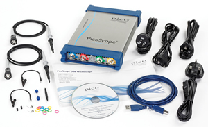
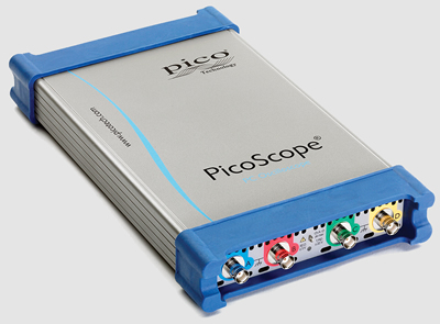
What's in the kit
- PicoScope 6000 Series oscilloscope
- 4 x 10:1 oscilloscope probes
- USB cable
- Universal AC adaptor
- Tough carry case
- PicoScope oscilloscope software
- Free software updates
• 5 GS/S Sampling
- 2 GSample Buffer Memory
- Arbitrary Waveform Generator
- SuperSpeed USB 3.0 Interface
- Advanced Triggers
- Mask Limit Testing
- Serial Bus Decoding … all as standard!
memory for long time capture at high sample rates.
Hardware acceleration, coupled with a SuperSpeed USB 3.0
interface, means that the PicoScope 6000 series oscilloscopes
can maintain fast update rates, even with long memory enabled.
| Oscilloscope | Model | Channels | Bandwidth | Sampling Rate | Buffer Memory |
Resolution (Enhanced) |
Price* |
|---|---|---|---|---|---|---|---|
| PicoScope 6402C | PP884 | 4 + AUX input & FuncGen | 250 MHz | 5 GS/s | 256 MS | 8 bits (12 bits) |
NZ$*
|
| PicoScope 6402D | PP885 | 4 + AUX input & AWG | 250 MHz | 5 GS/s | 512 MS | 8 bits (12 bits) |
NZ$*
|
| PicoScope 6403C | PP886 | 4 + AUX input & FuncGen | 350 MHz | 5 GS/s | 512 MS | 8 bits (12 bits) |
NZ$*
|
| PicoScope 6403D | PP887 | 4 + AUX input & AWG | 350 MHz | 5 GS/s | 1 GS | 8 bits (12 bits) |
NZ$*
|
| PicoScope 6404C | PP888 | 4 + AUX input & FuncGen | 500 MHz | 5 GS/s | 1 GS | 8 bits (12 bits) |
NZ$*
|
| PicoScope 6404D | PP889 | 4 + AUX input & AWG | 500 MHz | 5 GS/s | 2 GS | 8 bits (12 bits) |
NZ$*
|
| PicoScope 6407 USB Digitizer† | PP795 | 4 + AUX input & AWG | 1 GHz | 5 GS/s | 1 GS | 8 bits (12 bits) |
NZ$*
|
†The PicoScope 6407 digital oscilloscope / digitizer has a fixed �100 mV input range with SMA type connectors. Other products in this range are general purpose digital oscilloscopes.
High Bandwidth, High Sampling Rate
With 250 MHz to 500 MHz analog bandwidths complemented by a real-time sampling rate of 5 GS/s, the PicoScope 6000 Series scopes can display single-shot pulses with 200 ps time resolution. Equivalent time sampling (ETS) mode boosts the maximum sampling rate to 50 GS/s, giving an even finer timing resolution of 20 ps for repetitive signals.
Huge Buffer Memory
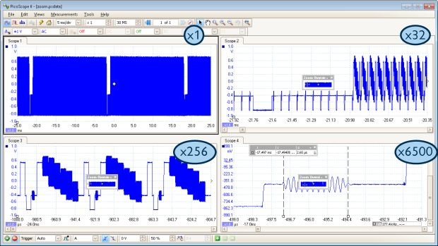
The PicoScope 6000 Series gives you the deepest buffer memory available as standard on any oscilloscope at any price. The SuperSpeed USB 3.0 interface and hardware acceleration ensures that the display is smooth and responsive even with long captures. Other oscilloscopes have high maximum sampling rates, but without deep memory they cannot sustain these rates on long timebases. The 2-gigasample buffer on the PicoScope 6404D can hold two 200 ms captures at the maximum sampling rate of 5GS/s. To help manage all this data, PicoScope can zoom up to 100 million times using a choice of two zoom methods. There are zoom buttons as well as an overview window that lets you zoom and reposition the display by simply dragging with the mouse.
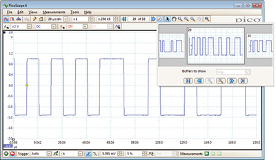
Store up to 10,000 waveforms in the buffer
Ever spotted a glitch on a waveform, but by the time you've stopped the scope it has gone? With PicoScope you no longer need to worry about missing glitches or other transient events.
With PicoScope you can divide the buffer memory into as many as 10,000 individually triggered segments. If you manage to completely fill the waveform buffer PicoScope will use the first in, first out principle to ensure that the buffer always contains the latest waveforms.
Arbitrary Waveform and Function Generator
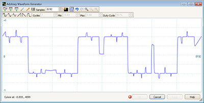
Every model includes a built-in DC to 20 MHz function generator with sine, square, triangle and DC waveforms. D models add a built-in 12-bit, 200 MS/s arbitrary waveform generator with a 64,000 sample buffer memory. You can import arbitrary waveforms from data files, oscilloscope waveforms or create and modify them using the built-in graphical AWG editor.
Analog and digital low-pass filtering
Each input channel has its own digital low-pass filter with independently adjustable cut-off frequency from 1 Hz to the full scope bandwidth. This enables you to reject noise on selected channels while viewing high-bandwidth signals on the others. An additional selectable analog bandwidth limiter on each input channel can be used to reject high frequencies that would otherwise cause aliasing.
Digital Triggering
Most digital oscilloscopes sold today still use an analog trigger architecture based on comparators. This can cause time and amplitude errors that cannot always be calibrated out. The use of comparators often limits the trigger sensitivity at high bandwidths. In 1991 Pico pioneered the use of fully digital triggering using the actual digitized data. This technique reduces trigger errors and allows our oscilloscopes to trigger on the smallest signals, even at the full bandwidth. Trigger levels and hysteresis can be set with high precision and resolution.
Digital triggering also reduces re-arm delay and this, combined with the segmented memory, allows the triggering and capture of events that happen in rapid sequence. At the fastest timebase you can use rapid triggering to collect 10,000 waveforms in under 10 milliseconds. The mask limit testing function can then scan through these waveforms to highlight any failed waveforms for viewing in the waveform buffer.
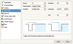
Advanced Triggers
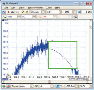
As well as the standard range of triggers found on most oscilloscopes, the PicoScope 6000 Series has a built-in set of advanced triggers to help you capture the data you need. All triggering is digital, resulting in high threshold resolution with programmable hysteresis and optimal waveform stability.
High Signal Integrity
Most oscilloscopes are built down to a price; ours are built up to a specification.
Careful front-end design and shielding reduces noise, crosstalk and harmonic distortion. Years of oscilloscope experience leads to improved pulse response and bandwidth flatness
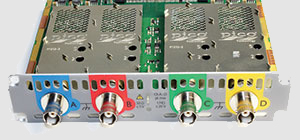
The result is simple: when you probe a circuit, you can trust in the waveform you see on the screen.
Hardware acceleration
On some oscilloscopes, enabling deep memory has a penalty: the screen update rate slows down and the controls become unresponsive as the processor struggles to cope with the amount of data. Thanks to the hardware acceleration inside PicoScope deep-memory oscilloscopes, you can collect waveforms containing hundreds of millions of samples while keeping fast screen update rates and a responsive user interface.
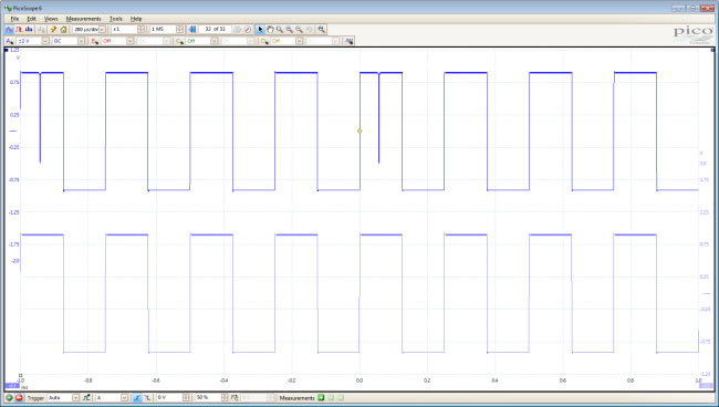
Dedicated hardware inside the oscilloscope processes multiple streams of data in parallel to construct the waveform that will be displayed on the screen. This is done far faster than any PC processor could manage, and together with USB 3.0 SuperSpeed data transfer eliminates any bottlenecks between the oscilloscope and the PC.
For example, the scope may be set to capture 100,000,000 samples but the PicoScope display window may be only 1000 pixels wide. In this case, the scope intelligently compresses the data into 1000 blocks of 100 000 samples each. Unlike simple decimation, which throws away most of the data, PicoScope hardware acceleration guarantees that you see any high-frequency details such as narrow glitches, even when the display is zoomed out.
a comprehensive suite of software that enables you to get the most from your scope.
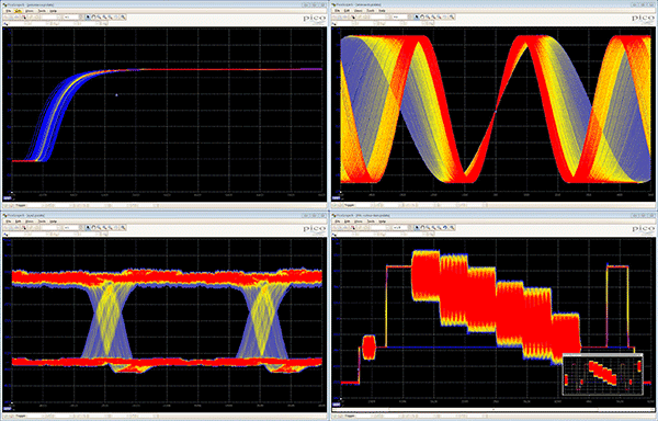
Colour Persistence Modes
See old and new data superimposed, with new data in a brighter color or shade. This makes it easy to see glitches, jitter,noise, trends and dropouts and estimate their relative frequency or occurence. Choose between analog persistence, digital color or custom display modes.
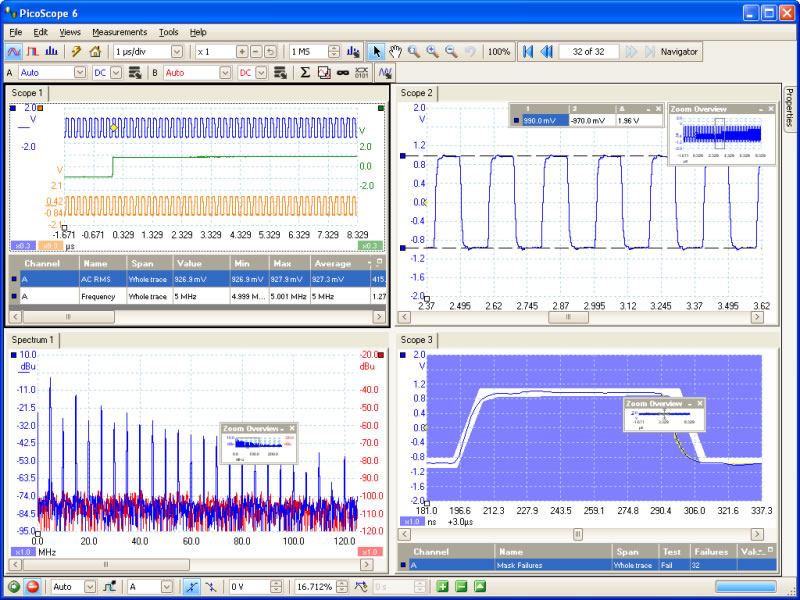
Start PicoScope software, click Auto setup and your PC is transformed into a powerful large screen oscilloscope with the timebase and triggering already set up.
Click Persistence mode and you can emulate the phosphor display of a conventional analog scope - useful for displaying complex analog signals and spotting glitches. Click Spectrum mode and your PC becomes an FFT spectrum Analyser. And there's more.
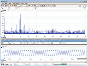
Spectrum Analyser
With the click of a button you can display a spectrum plot of the selected channels. The spectrum analyser allows signals up to the full bandwidth of the oscilloscope to be viewed in the frequency domain. A full range of settings gives you control over the number of spectrum bands, window type and display mode: instantaneous, average, or peak-hold.
You can display multiple spectrum views with different channel selections and zoom factors, and place these alongside time-domain views of the same data. A comprehensive set of automatic frequency-domain measurements, including THD, THD+N, SNR, SINAD and IMD, can be added to the display.
Mask Limit Testing
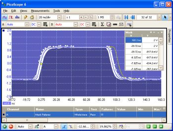
This feature is ideal for production and debugging environments. Capture a signal from a known working system, and PicoScope will draw a mask around it with your specified vertical and horizontal tolerances. Connect the system under test, and PicoScope will highlight any parts of the waveform that fall outside the mask area. The highlighted details persist on the display, so the scope can catch intermittent glitches even while your attention is elsewhere. The measurements window counts the number of failures, and can display other measurements and statistics at the same time. The numerical and graphical mask editors (both shown below) can be used separately or in combination, allowing you to enter accurate mask specifications or modify existing masks. You can import and export masks as files.
Serial Decoding
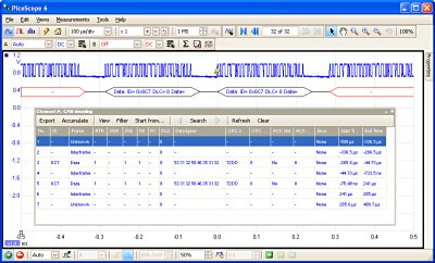
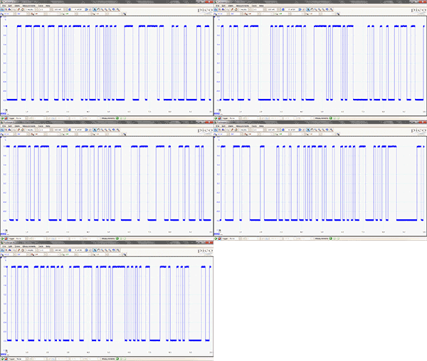
The PicoScope 6000 Series oscilloscopes are ideal for serial decoding, with a deep memory buffer that allows them to collect long, uninterrupted sequences of data. This allows the capture of thousands of frames or packets of data over several seconds. The scopes can decode up to four buses simultaneously with independent protocol selection for each input channel.
PicoScope displays the decoded data in the format of your choice: in view, in window, or both at once.
- In view format shows the decoded data beneath the waveform on a common time axis, with error frames marked in red. You can zoom in on these frames to look for noise or distortion on the waveform.
- In window format shows a list of the decoded frames, including the data and all flags and identifiers. You can set up filtering conditions to display only the frames you are interested in, search for frames with specified properties, or define a start pattern that the program will wait for before it lists the data.
Currently PicoScope can decode I2C, RS232/UART, SPI, I2S, FlexRay, LIN and CAN bus data. Expect this list to grow over time with future software upgrades.
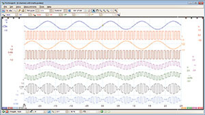
Maths Channels
With PicoScope 6 you can perform a variety of mathematical calculations on your input signals. You can calculate the sum, difference, product or inverse, or create your own custom function using standard arithmetic, exponential and trigonometric functions.
Resolution Enhancement
Resolution enhancement is a technique for increasing the effective vertical resolution of the scope at the expense of high–frequency detail.
Resolution enhancement adds up to four bits to the effective resolution of your oscilloscope, so a PicoScope 6000 can deliver up to 12 effective bits.
Automatic Measurements
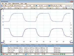
PicoScope allows you to automatically display a table of calculated measurements for troubleshooting and analysis. Using the built-in measurement statistics you can see the average, standard deviation, maximum and minimum of each measurement as well as the live value. You can add as many measurements as you need on each view.
For information on the measurements available in scope and spectrum modes, see automatic measurements in the specifications table.
Custom Probe Settings
The custom probes menu allows you to correct for gain, attenuation, offsets and nonlinearities of probes and transducers, or convert to different measurement units. Definitions for standard Pico-supplied probes are built in, but you can also create your own using linear scaling or even an interpolated data table.
High speed data acquisition / SDK
The drivers and software development kit supplied allow you to write your own software or interface to popular third-party software packages. If the 2 GS buffer memory of the PicoScope 6404D isn't enough, the drivers support data streaming, a mode that captures gap-free continuous data over the USB 3.0 port directly to the PC's RAM at over 150 MS/s. Rates are subject to PC specifications and application loading.
| Oscilloscope Vertical | ||||||
|---|---|---|---|---|---|---|
| Model | PicoScope6402C (PP884) |
PicoScope 6402D (PP885) |
PicoScope 6403C (PP886) |
PicoScope 6403D (PP887) |
PicoScope 6404C (PP888) |
PicoScope 6404D (PP889) |
| Analog Bandwidth* (-3dB) | 250 MHz, 200 MHz (±50 mV range) | 350 MHz, 250 MHz (±50 mV range) | 500 MHz (all ranges) | |||
| Hardware Bandwidth limiter | Switchable, 20 MHz | Switchable, 25 MHz | ||||
| Rise time (10% to 90%, calculated) |
1.4 ns (50 mV range 1.8 ns) | 1.0 ns (50 mV range 1.4 ns) | 0.7 ns (all ranges) | |||
| Vertical resolution | 8 bits | |||||
| Enhanced vertical resolution | 12 bits | |||||
| Input sensitivity | 10 mV/div to 4 V/div at x1 zoom (1 MΩ input), 10 mV/div to 1 V/div at x1 zoom (50 Ω input) | |||||
| Input ranges (full scale) | ±50 mV to ±20V, in 9 ranges (1 MΩ input) ±50 mV to ±5V, in 7 ranges (50 Ω input) |
|||||
| Input characteristics | 1 MΩ in parallel with 15 pF (AC or DC coupling) or 50 Ω (DC coupling) | 1 MΩ in parallel with 10 pF (AC or DC coupling) or 50 Ω (DC coupling) | ||||
| Analogue offset range 50 mV to 200 mV 500 mV range 1 V range 2 V range 5 V range 10 V range 20 V range |
Available offset ±0.5 V ±2.5 V ±2.5 V ±2.5 V ±20 V (50 Ω ±0.5 V) ±20 V ±20 V |
Available offset ±2 V ±10 V (50 Ω ±5 V) ±10 V (50 Ω ±4.5 V) ±10 V (50 Ω ±3.5 V) ±35 V (50 Ω ±0.5 V) ±30 V ±20 V |
||||
| DC Accuracy | 3% of full scale | |||||
| Input type | Single ended, BNC connector | |||||
| Overload protection | ±100V to ground (1MΩ inputs), 5.5V RMS (50Ω inputs) | |||||
| Dynamic Performance | ||
|---|---|---|
| Noise | 200 μV RMS (50 mV range) | 320 μV RMS (50 mV range) |
| THD | –55 dB typical | –54 dB typical |
| SFHR | 60 dB typical | 55 dB typical |
| Crosstalk | 17 000:1 typical at 20 MHz, 1000:1 typical at full bandwidth | 5600:1 typical at 20 MHz 560:1 typical at full bandwidth |
| Oscilloscope Horizontal | ||||||
|---|---|---|---|---|---|---|
| Maximum Sampling Rate (single shot) One channel in use Two channels in use 3 or 4 channels in use |
5GS/s 2.5GS/s 1.25GS/s |
|||||
| Maximum Sampling Rate (repetitive signals) | 50 GS/s | |||||
| Maximum Sampling Rate (continuous streaming mode) |
10 MS/s using PicoScope. >150 MS/s using the supplied SDK (PC dependent) | |||||
| Buffer Size (shared between active channels) |
256 MS |
512 MS |
512 MS |
1 GS |
1 GS |
2 GS |
| Buffer Size (streaming mode) | 100 MS in PicoScope software. Up to available PC memory when using SDK. | |||||
| Max. Buffer Segments (using PicoScope 6) | 10,000 | |||||
| Maximum Buffer Segments (using SDK) | 250,000 | 500,000 | 500,000 | 1,000,000 | 1,000,000 | 2,000,000 |
| Timebase Ranges Real time ETS | 1 ns/div to 5000 s/div 50 ps/div to 100 ns/div | |||||
| Timebase Accuracy | ±2 ppm | |||||
| Timebase Ageing | 1 ppm per year | |||||
| Triggers | |
|---|---|
| Basic triggers | Rising, falling |
| Advanced triggers |
Edge: single edge or dual edge; adjustable hysteresis Pulse width: negative or positive pulse; wider or narrower than a specified width Window: entering or leaving a voltage range Window pulse width: signal is inside or outside a voltage range for a set time Dropout: inactivity over a user defined time interval Window dropout: signal does not enter or exit a voltage range for at least a set time Delay: nth event after trigger event, with optional delay Interval: time between two edges is greater or less than a set time, or inside/outside a time range Level: the signal remains on one side of a threshold voltage for a specified period of time Logic level: arbitrary logic state of Channels A to D and AUX Runt pulse: crosses one threshold but not the other |
| Trigger Modes | None, Single, Repeat, Auto, Rapid, ETS |
| Maximum Trigger Rate | Up to 10,000 waveforms in a 10 ms burst |
| Trigger Sources | Channels A to D, AUX |
| Trigger Level | Adjustable over whole of selected voltage range |
| Trigger Sensitivity | 1 LSB accuracy up to full bandwidth of scope |
| Re Arm Time | Less than 1µs on fastest timebase |
| Maximum Pre Trigger Capture | 100% of capture duration |
| Maximum Post Trigger Delay | 4 billion samples |
| Trigger Timing Resolution | 1 sample period |
| Auxiliary Trigger Input (AUX) | |
|---|---|
| AUX Trigger Connector Type | Rear panel BNC, shared with reference clock input |
| Trigger Types | Edge, pulse width, dropout, interval, logic |
| Input Characteristics | 50 Ω ±1%, DC coupled |
| Bandwidth | 25 MHz |
| Threshold Range | ±1 V |
| Overvoltage Protection | ±5 V (DC + AC peak) |
| Reference Clock Input (SDK only) | |
|---|---|
| Clock Input Characteristics | 50 Ω, BNC, ±1 V, DC coupled |
| Frequency Range | 5, 10, 20, 25 MHz, user-selectable |
| Connector | Rear panel BNC, shared with AUX trigger |
| Level | Adjustable threshold, ±1 V |
| Overvoltage Protection | ±5 V |
| Function Generator and Arbitrary Waveform Generator | ||||||
|---|---|---|---|---|---|---|
| Frequency Range | DC to 20 MHz | |||||
| Standard Waveforms All Models D Models |
Sine, square, triangle, DC level Sine, square, triangle, DC level, ramp (up/down), sin (x)/x, Gaussian, half sine, white noise, PRBS, |
|||||
| Output Frequency Accuracy | Same as scope timebase accuracy | |||||
| Output Frequency Resolution | < 0.05 Hz | |||||
| DC Accuracy | ±1% of full scale | |||||
| Connector Type | Rear panel BNC | |||||
| Overvoltage Protection | ±5 V | |||||
| Sweep Modes | Up, down, or dual, with selectable start/stop frequencies and increments | |||||
| Signal Generator Triggering | Scope, manual, or AUX input; programmable number of cycles from 1 to 1 billion | |||||
| Amplitude Range | ±250 mV to ±2 V | |||||
| Offset Adjustment | ±1 V (maximum combined output ±2.5 V) | |||||
| Output Impedance | 50Ω | |||||
| AWG Buffer Size | n/a | 64 kS | n/a | 64kS | n/a | 64kS |
| AWG Sample Rate | n/a | 200 MS/s | n/a | 200 MS/s | n/a | 200 MS/s |
| AWG Resolution | n/a | 12 bits | n/a | 12 bits | n/a | 12 bits |
| Probe Compensation Output | |
|---|---|
| Signal Output Type | 1 kHz square wave, 2 V pk~pk, 600 Ω |
| Spectrum Analyser | |||
|---|---|---|---|
| Frequency Range | DC to 250MHz | DC to 350MHz | DC to 500MHz |
| Display Modes | Magnitude, peak hold, average | ||
| Windowing Functions | Rectangular, Gaussian, triangular, Blackman, Blackman Harris, Hamming, Hann, flat top | ||
| Number of FFT Points | Selectable from 128 to 1,048,576 | ||
| Software | |
|---|---|
| PicoScope 6 for Windows | |
| Linux Drivers | 32 bit drivers |
| Software Development Kit | A growing collection of drivers and example code for various programming languages |
| PC Requirements | |
|---|---|
| Minimum |
Processor: 1GHz Memory: 512MB Free Disk Space: 32-bit: 600 MB, 64-bit: 1.5 GB Operating system: 32 or 64 bit edition of Microsoft Windows XP (SP3), Vista, Windows 7 or Windows 8 (not Windows RT) Ports: USB 2.0 compliant port |
| Recommended |
Processor: 1GHz Memory: 512MB Free Disk Space: 32-bit: 600 MB, 64-bit: 1.5 GB Operating system: 32 or 64 bit edition of Microsoft Windows XP (SP3), Vista, Windows 7 or Windows 8 (not Windows RT) Ports: USB 3.0 compliant port |
| Environmental | |||
|---|---|---|---|
| Operating environment Temperature range |
0°C to 40°C (20°C to 30°C for quoted accuracy) |
||
| Storage environment Temperature range Humidity |
-20°C to +60°C 5% to 95% RH, non condensing |
||
| Physical Dimensions | ||
|---|---|---|
| Dimensions | 255 x 170 x 40mm (approx 10 x 6.7 x 1.6in) | 280 x 170 x 40mm (approx 11 x 6.7 x 1.6in) |
| Weight | 1kg (approx 2 lb 3 oz) | 1.3 kg (approx 2 lb 14 oz) |
| General | |
|---|---|
| Power supply AC adaptor | AC adaptor 12V ±2V @ 3.5A External adaptor supplied (suitable for USA, UK, Europe and Australasia) |
| Compliance | FCC, CE,RoHS compliant |
| Accessories Included | |
|---|---|
| Additional Hardware (supplied) | Four factory–compensated oscilloscope probes, USB 3.0 cable, universal mains (AC) power supply, mains lead (power cord), carry case and user manuals |
| Software | PicoLog & PicoScope 6 CD ROM |
| Documentation | User's guide, Programmer's guide & Installation guide |
